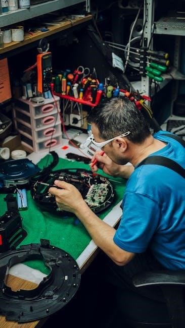
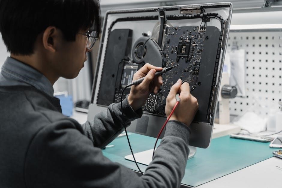
CDI Electronics is a critical component in modern ignition systems‚ utilizing capacitor discharge technology to generate high voltage sparks. It enhances engine performance‚ fuel efficiency‚ and reduces emissions by ensuring precise and powerful ignition. Its reliability and efficiency make it indispensable in various applications‚ replacing traditional ignition systems.

1.1 Understanding CDI Technology and Its Role in Modern Engines
CDI (Capacitor Discharge Ignition) technology uses a capacitor to store electrical energy‚ releasing it rapidly to generate high-voltage sparks. This system ensures precise ignition timing and reliable engine operation. Unlike traditional systems‚ CDI provides consistent sparks even at high RPM‚ improving performance and fuel efficiency. Modern engines rely on CDI for its ability to handle varying conditions‚ such as temperature changes and vibration. The digital control module in CDI systems enhances accuracy‚ making it a cornerstone of ignition systems in motorcycles‚ ATVs‚ and small engines. Its compact design and low maintenance further contribute to its widespread adoption in today’s combustion engines.
1.2 Benefits of CDI Systems Over Traditional Ignition Systems
CDI systems offer several advantages over traditional ignition systems‚ including higher voltage output for stronger sparks‚ improved fuel efficiency‚ and reduced engine wear. They provide consistent ignition performance across varying RPM ranges‚ ensuring reliable engine operation. Unlike points-based systems‚ CDI units require less maintenance and are less prone to mechanical failure. Additionally‚ CDI systems reduce electromagnetic interference and offer better resistance to heat and vibration. Their compact design also makes them easier to integrate into modern engines. Overall‚ CDI systems enhance engine performance‚ reliability‚ and longevity‚ making them a preferred choice for motorcycles‚ ATVs‚ and other small combustion engines.

Common Issues in CDI Electronics
Common issues include no spark‚ intermittent spark‚ engine shut-off‚ and ignition coil failures. These problems often stem from faulty components‚ wiring faults‚ or heat-related damage.
2.1 No Spark or Intermittent Spark at the Spark Plug
No spark or intermittent spark at the spark plug is a common issue in CDI systems. This can occur due to faulty ignition coils‚ poor connections‚ or failed power supply to the ignition coil. Intermittent spark may develop when the engine is warm‚ indicating heat-related component failure. Checking the ignition coil ground and ensuring proper wiring connections is essential. Additionally‚ testing the stator and trigger sensor can identify underlying issues. If the spark disappears after warming up‚ it often points to a failing CDI unit or ignition coil. Addressing these problems promptly prevents further damage to the ignition system.
2.2 Engine Shut-Off or Failure to Start
Engine shut-off or failure to start is often linked to CDI system malfunctions. A faulty stator‚ ignition coil‚ or sensor can disrupt the ignition process‚ causing the engine to stall or not start. Intermittent operation may occur due to heat-related failures in components. Checking the kill switch‚ ignition wiring‚ and connectors is crucial. Ensure the CDI unit receives proper power and ground. If the engine shuts down unexpectedly‚ inspect the wiring harness for grounding issues or short circuits. Testing the stator’s resistance and voltage output can identify failures. Addressing these issues promptly prevents prolonged downtime and potential damage to the engine.
2.3 Ignition Coil Failures and Their Symptoms
Ignition coil failures are common in CDI systems‚ often causing intermittent or complete loss of spark. Symptoms include engine misfires‚ rough idling‚ and decreased performance. A faulty coil may produce a weak spark‚ leading to poor combustion. Physical signs like cracks‚ burns‚ or damaged insulation on the coil indicate failure. Testing the coil’s primary and secondary resistance with a multimeter can diagnose issues. Additionally‚ checking the coil’s ground connection and power supply is essential. A failing coil may also cause the engine to shut off unexpectedly‚ especially under load or at high temperatures. Replacing the ignition coil is typically the solution.
Diagnostic Steps for CDI Electronics
Diagnosing CDI issues involves checking ignition switches‚ wiring‚ and spark plugs. Testing stator resistance and coil voltage is crucial. Use multimeters and oscilloscopes for precise measurements and waveform analysis.

3.1 Preliminary Checks: Ignition Switch‚ Kill Switch‚ and Wiring
Begin troubleshooting by inspecting the ignition and kill switches. Ensure they function correctly and are not stuck or damaged. Check wiring connections for corrosion‚ cuts‚ or loose terminals. Verify proper continuity using a multimeter‚ focusing on the ignition coil circuit. Grounding issues are common‚ so test for unintended ground paths. Ensure the ignition switch provides power to the CDI module when in the “on” position. Similarly‚ confirm the kill switch interrupts power correctly. Faulty wiring or switches can mimic other issues‚ so resolving these first is essential for accurate diagnosis. Clean or replace components as needed to restore proper electrical flow.

3.2 Testing the Ignition Coil and Spark Plug
Start by testing the ignition coil using a multimeter to measure resistance across the primary and secondary windings. Compare readings to the manufacturer’s specifications. Check for continuity in the primary circuit and ensure the coil is properly grounded. Use a spark tester to verify spark presence without removing the spark plug. If no spark is detected‚ inspect the spark plug for fouling or wear. Ensure the spark plug gap is within specified limits. If issues persist‚ test the coil’s voltage output using an oscilloscope. A faulty ignition coil or spark plug can prevent proper combustion‚ leading to engine misfires or failure to start.
To test the stator resistance‚ use a multimeter set to the ohms function. Consult your vehicle’s service manual for the correct terminals and expected resistance values. Disconnect the stator from the CDI unit for an accurate reading. If the resistance is out of spec‚ it may indicate worn windings. For voltage testing‚ measure the stator’s output with the engine running‚ typically between 50 to 200 volts AC‚ depending on RPM. Ensure the wiring harness is inspected for corrosion or damage. If possible‚ use an oscilloscope to analyze the waveform for interference. Proper testing ensures the CDI unit receives the necessary power for reliable ignition.
Essential Tools for CDI Troubleshooting
3.3 Stator Resistance and Voltage Testing
Use a multimeter to measure stator resistance‚ ensuring it matches the manufacturer’s specifications. Test voltage output at the stator terminals while the engine runs. Verify wiring integrity and check for short circuits. If resistance is too high or low‚ replace the stator. For voltage‚ expect 50-200V AC‚ depending on RPM. Inspect connections and wiring for corrosion or damage. Use an oscilloscope to analyze the waveform for interference or irregularities. Proper testing ensures the CDI unit receives the correct power‚ preventing ignition issues. Always consult the service manual for specific values and procedures to avoid incorrect diagnoses or component damage.
4.1 Multimeter for Measuring Resistance and Voltage
A multimeter is essential for CDI electronics troubleshooting‚ enabling precise measurements of resistance and voltage. Use it to test the ignition coil’s primary and secondary resistance‚ ensuring values align with the manufacturer’s specifications. Measure voltage at the coil’s power supply and ground connections to identify power issues. Additionally‚ test the stator’s resistance to detect internal faults. Set the multimeter to DC voltage mode to verify the ignition coil’s power supply and ground integrity. Always compare readings to the service manual. If readings deviate‚ it indicates potential component failure or wiring issues. This tool is vital for diagnosing no-spark or intermittent-spark problems accurately.
4.2 Oscilloscope for Analyzing Waveforms
An oscilloscope is a powerful tool for advanced CDI troubleshooting‚ allowing visualization of electrical waveforms. It captures the ignition coil’s voltage pulses and stator signals over time‚ revealing irregularities. Connect the oscilloscope to key components like the ignition coil or stator. Set appropriate voltage and time scales to observe waveforms. Compare captured patterns to a known good waveform to identify deviations. This helps diagnose issues such as faulty triggers‚ stator malfunctions‚ or ignition coil failures. Oscilloscope analysis is crucial for pinpointing intermittent problems and verifying repairs. It provides deeper insights into the system’s electrical behavior‚ aiding precise diagnostics beyond basic multimeter tests.
4.3 CDI Tester for Advanced Diagnosis
A CDI Tester is a specialized diagnostic tool designed to evaluate the performance of CDI systems comprehensively. It simulates engine conditions to test the ignition coil‚ stator‚ and wiring harness. The tester can identify issues such as faulty triggers‚ low voltage outputs‚ or grounding problems. Advanced models provide real-time data and error codes‚ aiding precise fault detection. Regular use ensures early identification of potential failures‚ preventing engine shutdowns. Shops often rely on CDI Testers for accurate diagnoses‚ reducing repair time and costs. This tool is essential for professionals seeking to troubleshoot complex ignition system malfunctions efficiently and effectively‚ ensuring optimal engine performance and reliability.

Advanced Troubleshooting Techniques
Advanced troubleshooting involves waveform analysis‚ intermittent fault detection‚ and load testing. These methods help identify elusive issues like faulty sensors or wiring faults under specific conditions.
5.1 Checking the Wiring Harness for Grounding Issues
Inspecting the wiring harness for grounding issues is crucial in CDI troubleshooting. Faulty ground connections can prevent proper signal transmission‚ leading to ignition failures. Using a multimeter‚ check for continuity between ground wires and the frame. Ensure no wires are pinched or corroded‚ as this can cause intermittent sparks. Corrosion at connectors should be cleaned to maintain conductivity. If a ground fault is detected‚ repair or replace the affected section to restore system functionality. Proper grounding ensures reliable communication between components‚ essential for consistent engine operation.
5.2 Testing the Trigger and Timing Sensors
Testing the trigger and timing sensors is essential for diagnosing CDI issues. These sensors ensure proper ignition timing by detecting crankshaft position and rotation speed. Using a multimeter‚ verify the resistance and voltage of the sensors as per the service manual. Check for wiring issues‚ such as short circuits or loose connections. Symptoms of faulty sensors include intermittent sparks or poor engine timing. An oscilloscope can analyze sensor waveforms to identify distortions or irregular patterns. If the sensor fails testing‚ replace it to restore accurate ignition timing and engine performance. Proper sensor function is critical for reliable CDI operation and engine efficiency.
5.3 Using a Spark Tester for Accurate Spark Detection
A spark tester is a vital tool for diagnosing CDI systems. It helps verify the presence and strength of the spark at the spark plug or ignition coil. By simulating engine conditions‚ the tester can detect intermittent sparks or weak ignition signals. Place the tester near the spark plug or coil and observe the spark color and intensity. A strong blue spark indicates a healthy system‚ while a weak or yellow spark suggests issues like low voltage or faulty components. This tool is especially useful for identifying intermittent problems that may not appear during basic testing. Accurate spark detection ensures reliable engine operation and performance.
